

imx METIS Hardware
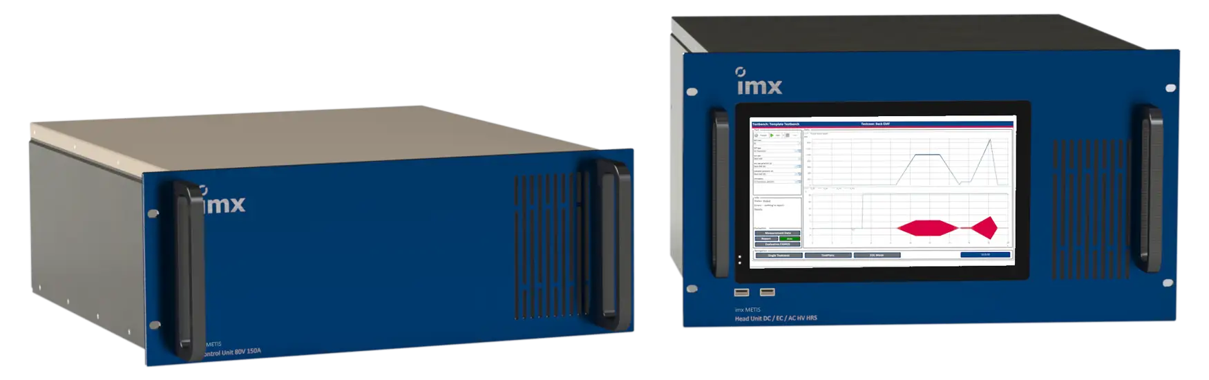
imx METIS is based on a modular and expandable hardware concept. Two functional modules handle all key system tasks.
The Head Unit is responsible for measurement data acquisition and test sequence control. The Control Unit includes the required control electronics and motor controllers, among other components. A safety PLC complements the system. Power supplies and uninterruptible power supplies for the PC and communication components complete the core hardware configuration.
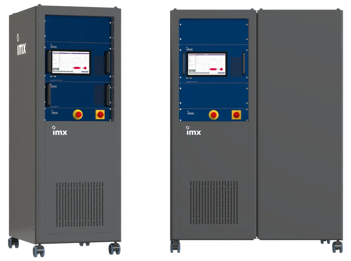
All components are integrated into a 19-inch cabinet, making every imx METIS solution a complete, ready-to-operate motor testing system.
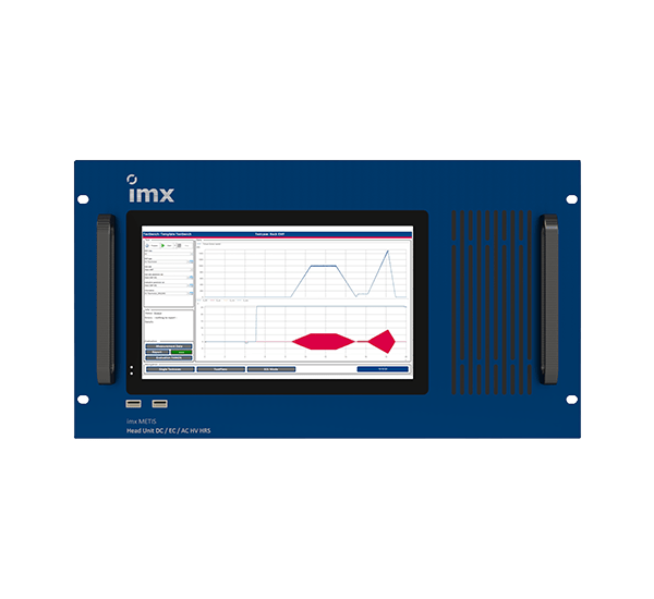
imx METIS Head Unit
The foundation of modern test architecture
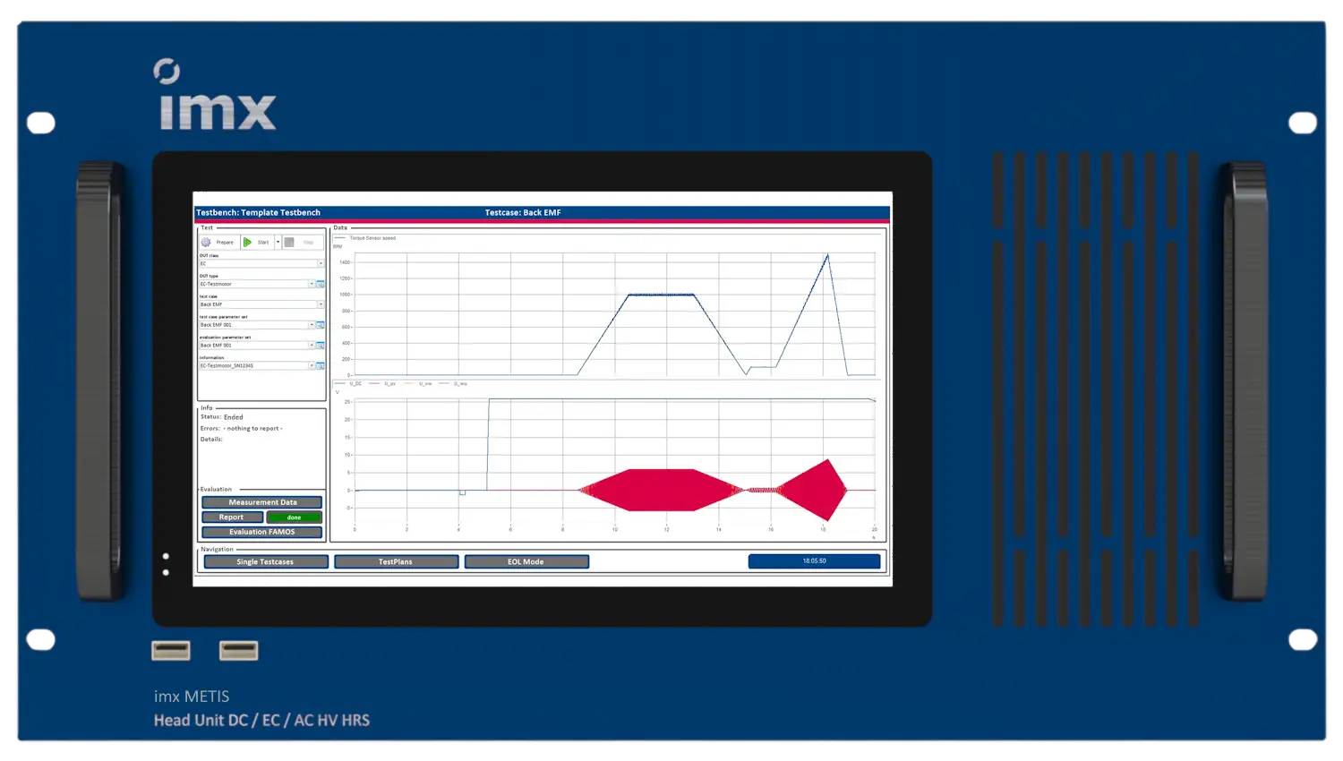
The Head Unit is at the heart of imx METIS and is responsible for measurement data acquisition and processing. Precision measurement inputs for voltage, current, and feedback signals provide the raw data used for evaluation and for building the motor model.
The modular sensor concept also enables measurements to be easily adapted to different motors under test. A dedicated expansion interface allows additional measurement modules and sensors – such as accelerometers for NVH analysis – to be seamlessly integrated into the test sequence.
- Predefined voltage and current ranges
- Measurement technology adapted to a wide range of feedback sensors
- Standardized interface to the Control Unit
- Peripheral interfaces for external devices such as power supplies and controllers
- Dedicated LAN ports for integration into customer networks
- Modular and expandable design
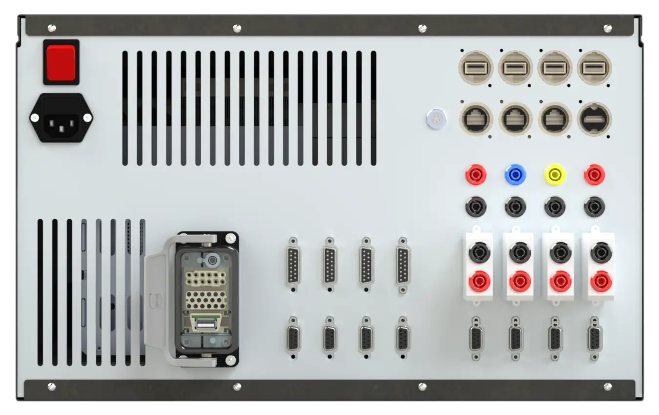
- Plug-in connection to the imx METIS Control Unit
- Plug-in connection to external inverters
- COM and Ethernet interfaces
- Connections for measurement inputs
- Power supply for additional measurement modules
- Proprietary EtherCAT interface
imx METIS Head Unit Variants
The standard variants of the imx METIS Head Unit cover all common voltage levels and power classes. Motors with nominal voltages ranging from just a few volts up to 1,000 V can be tested and characterized.
Depending on the selected variant, the imx METIS Head Unit can process feedback signals from encoders, Sin/Cos encoders, and resolvers.
imx METIS Control Unit
Dynamic precision at the motor
The Control Unit generates the excitation pattern used to characterize the motor under test. Highly dynamic excitation is essential for obtaining reliable and meaningful test results. Depending on the motor type and test requirements, the Control Unit provides the required voltages and currents.
For DC motors in lower power classes, the required power supply is integrated directly into the DC variant of the Control Unit. Higher power classes are supplied by external power sources. To ensure stable and reliable continuous operation, all power components are actively air-cooled.
Key features
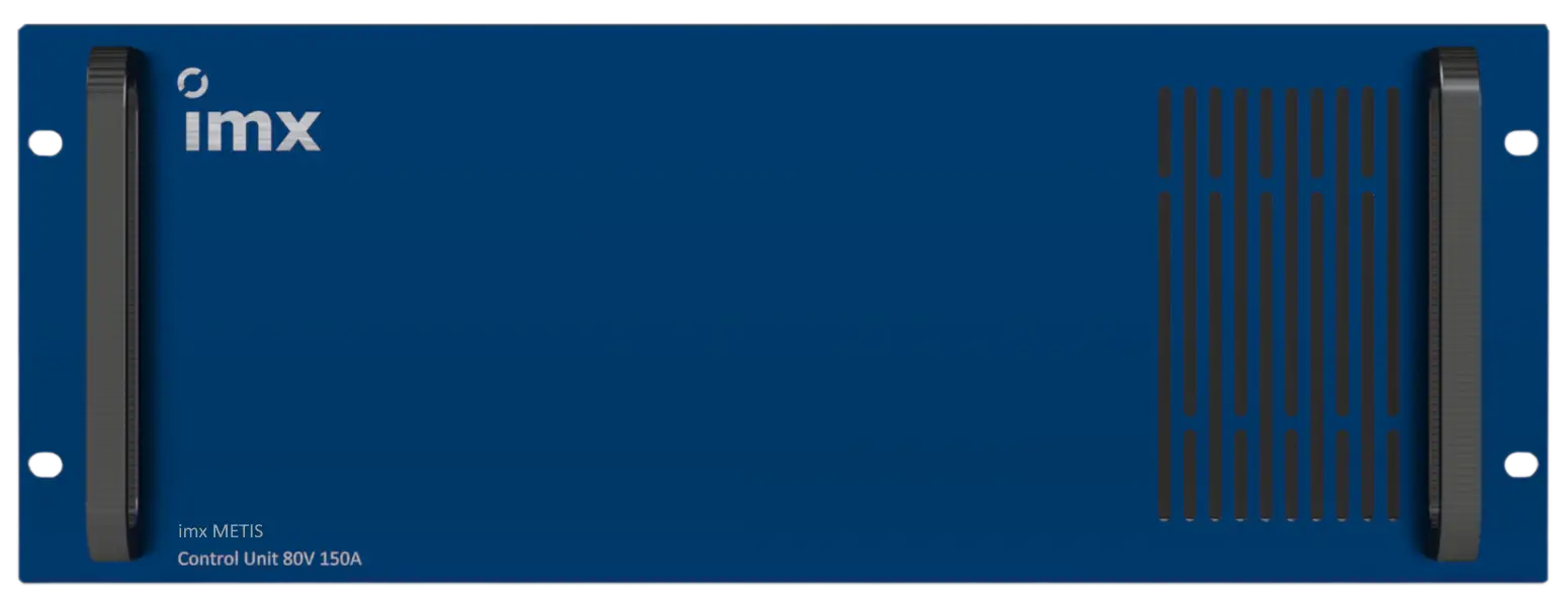
- Simple and clearly structured connection panel
- Pre-assembled cables and sensors
- Standardized interface to the Head Unit
- Calibration sockets for complete measurement traceability
- Integrated current sensors
- Variants for different voltage and current ranges
Connections and Interfaces
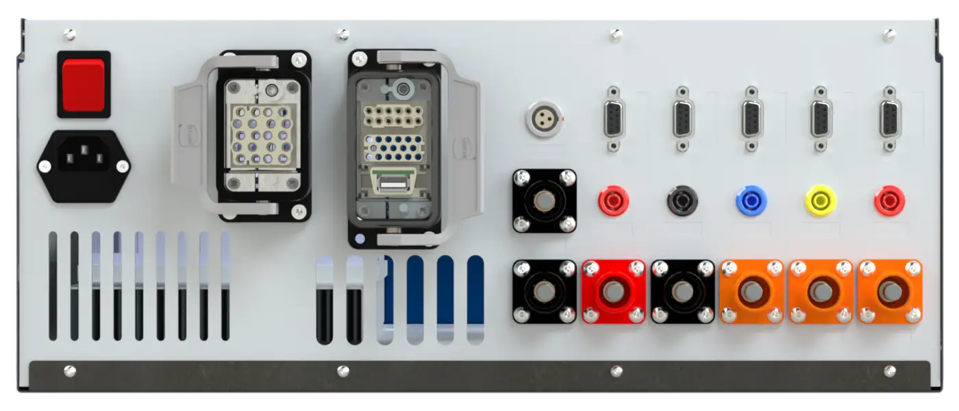
- Power connections for the motor supply
- Connections for feedback signals
- DC power supply
- Direct connection to the imx METIS Head Unit for feedback signal routing, control, and communication between both modules
imx METIS Control Unit Variants
The imx METIS Control Unit is available in different variants for DC and BLDC/EC motors, covering common voltage levels and power ranges.
The modules for BLDC/EC motors support various feedback systems for motor commutation, including encoders, Sin/Cos encoders, and digital encoders.
imx METIS System Configuration
Configuration with Control Unit
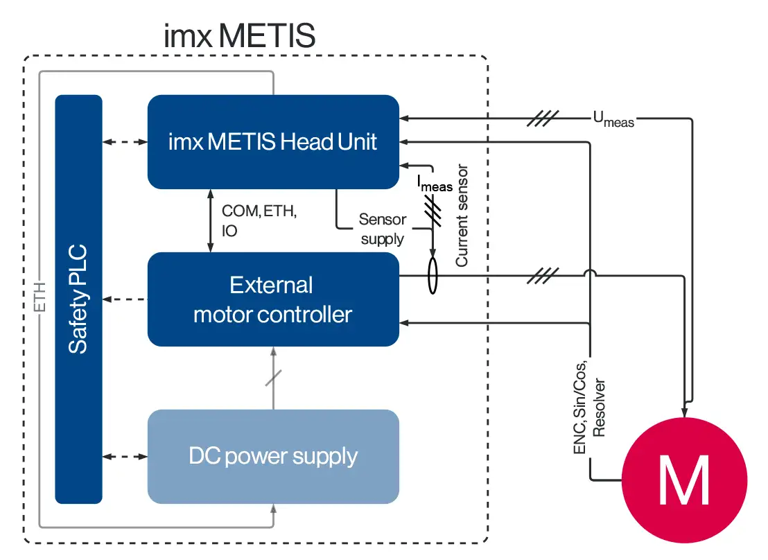
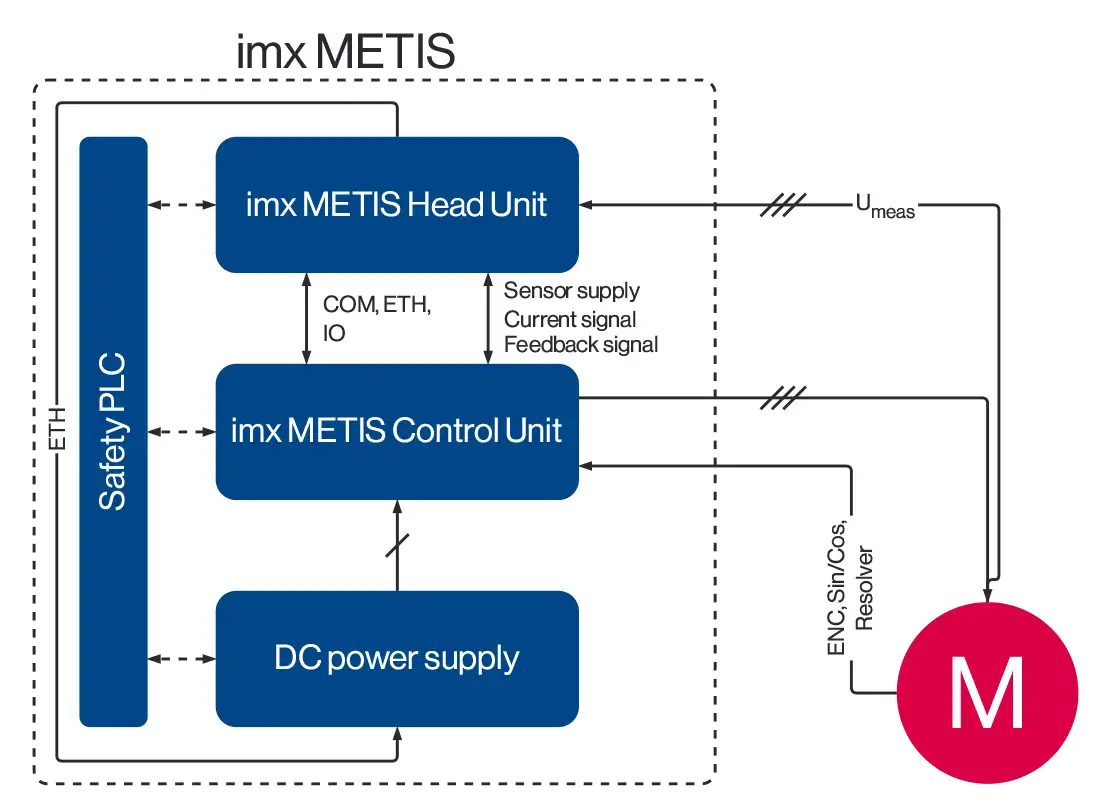
Setting up imx METIS with a Head Unit and Control Unit for DC and BLDC/EC motor testing is straightforward. Pre-assembled cables connect the modules, while the required sensors are integrated directly into the system.
The setup is complemented by a suitable controllable DC power supply, which is also controlled by the Head Unit.
The motor under test is connected to the Control Unit. Voltage measurement is performed as close to the motor as possible to minimize measurement deviations and ensure high measurement accuracy.
Configuration with External Inverter
When testing induction motors or high-power synchronous motors, suitable external inverters are used. In this configuration, the required sensors are integrated into the test setup and connected directly to the Head Unit.
If the inverter system requires a DC-link voltage, either integrated or external power supplies can be used.
This flexible architecture allows imx METIS to cover a wide range of motor types, voltage levels, and power classes while maintaining a consistent approach to measurement, data acquisition, and parameter identification.